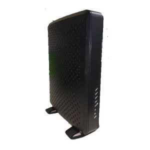
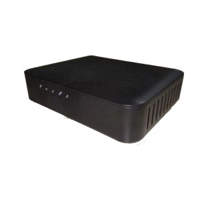
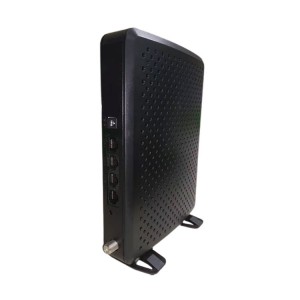
ECMM, DOCSIS 3.1, 4xGE, POE, 2xMCX, Digital Attenuator, MK440IE-P
Short Description:
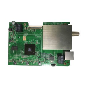
The MoreLink’s MK44IE-P is a DOCSIS 3.1 ECMM Module (Embedded Cable Modem Module) supporting 2×2 OFDM and 32×8 SC-QAM to deliver a powerful high-speed Internet experience. Temperature hardened design which is suitable for industrial applications.
The MK440IE-P is the perfect choice for cable operators who want to offer high-speed and economic broadband access to their customer base. It delivers speeds up to 4Gbps based on 4 Giga Ethernet ports over its DOCSIS interface. The MK440IE-P allows MSOs to offer their customers various broadband applications such as telecommuting, HD, and UHD video on demand over IP connectivity to a small oce/home oce (SOHO), high-speed residential Internet access, interactive multimedia services, etc.
Product Detail
Product Tags
Product Detail
The MoreLink’s MK44IE-P is a DOCSIS 3.1 ECMM Module (Embedded Cable Modem Module) supporting 2x2 OFDM and 32x8 SC-QAM to deliver a powerful high-speed Internet experience. Temperature hardened design which is suitable for industrial applications.
The MK440IE-P is the perfect choice for cable operators who want to offer high-speed and economic broadband access to their customer base. It delivers speeds up to 4Gbps based on 4 Giga Ethernet ports over its DOCSIS interface. The MK440IE-P allows MSOs to offer their customers various broadband applications such as telecommuting, HD, and UHD video on demand over IP connectivity to a small oce/home oce (SOHO), high-speed residential Internet access, interactive multimedia services, etc.
The MK440IE-P is an intelligent device that enhances its basic data transmission features with IPv6 support, which makes it especially suitable for the transmission of data based on this protocol.
Highlights
MK440IE-P is a cable modem compliant with the new DOCSIS® 3.1 Specifications, and provides 2 OFDM and 32 Single-Carrier QAM downstream with integrated 1.2 GHz Full Band Capture (FBC) front end, 2 OFDMA and 8 Single-Carrier QAM upstream channels. MK440IE-P is capable of supporting over 5 Gbps downstream and over 2 Gbps upstream.
Base on Full Band Capture (FBC) function, it is not only a Cable Modem, but also can be used as a real-time Spectrum Analyzer. The Spectrum Analyzer has many features which benefits operators, such as: proactive plant maintenance and on-line diagnosis; detect problems before customers realize them; remote LTE/off-air ingress detection and localization.
Provide 4-Port Giga Ethernet interfaces and complaint with Standard POE+ (IEEE 802.3at) and POE (IEEE 802.3 af), each POE port can be configured by separately.
The MK440IE-P is temperature hardened for integration in other products that are required to operate in the outdoor or extreme temperature environment.
Product Features
➢ DOCSIS / EuroDOCSIS 3.1 compliant
➢ 2x192MHz OFDM downstream reception capability
-4096 QAM support
➢ 32x SC-QAM (Single-Carries QAM) channel downstream reception capability
-1024 QAM support
-16 of 32 channels capable of enhanced de-interleaving for video support
➢ 2x96 MHz OFDMA upstream transmission capability
-256 QAM support
-S-CDMA and A/TDMA support
➢ FBC (Full Band Capture) Front End
-1.2 GHz Bandwidth
-Configurable to receive and channel in the downstream spectrum
-Supports fast channel change
-Real-time, diagnostic including spectrum analyzer functionality
➢ Digital Attenuators for Downstream and Upstream separately
➢ Standalone external watchdog design for high reliability
➢ Four Gigabit Ethernet Ports supporting IEEE 802.3at PoE
➢ Remote PoE Mode A/B switchable
➢ Tamper sensor
➢ Voltage, current petameters measurements
➢ Well-defined LEDs clearly display device and network status
➢ Software upgrade by HFC network
➢ SNMP V1/V2/V3
➢ Support baseline privacy encryption (BPI/BPI+)
Application
➢ IP Camera Video Surveillance
➢ Small Cell Backhaul
➢ Digital Signage
➢ Wi-Fi Hotspot Traffic
➢ Emergency broadcast
➢ Smart Cities
➢ Others which require business over DOCSIS
Technical Parameters
|
Basics |
|||||
| DOCSIS Standard | 3.1 | ||||
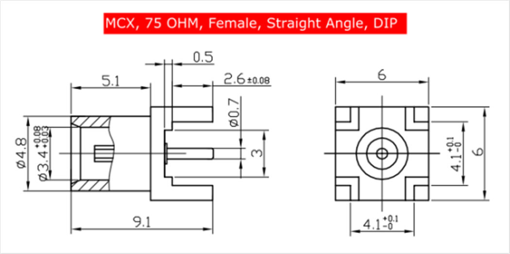
| RF Interface (DS+US, Separately) | MCX | ||||
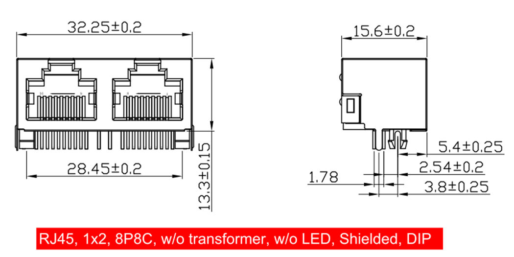
| Ethernet Interface | 4-Port RJ45, Right Angle | ||||
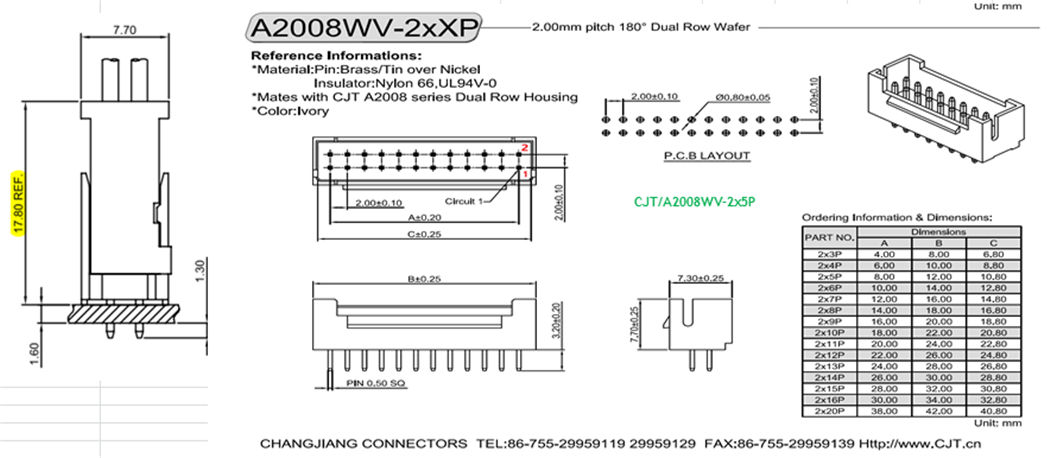
| Digital Attenuator Interface | 2-Port Digital Attenuator ControlWafer Header 2x7, 2.0mm, Straight Angle | ||||
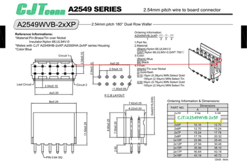
| Power Input | +12V /1A ; +54V/1.4AWafer Header 2x5, 2.54mm, Straight Angle | ||||
| Power Consumption (w/o POE) | 8(TYP.); 15(Max.) | W | |||
| Operating Parameters Monitor | Power Consumption of System; Tamper; Temperature; RF Power Level; Voltage/ Current /Class /Detect/ Attenuator | ||||
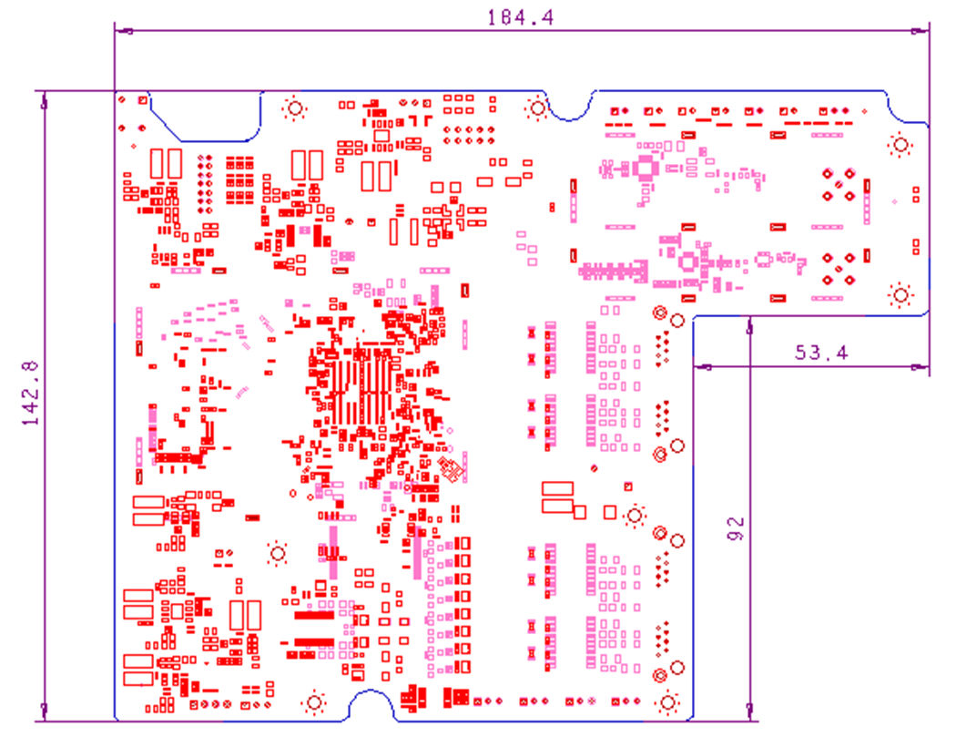
| Dimensional Size | 142.8 x 184.4 | ||||
| Downstream | ||
| Frequency Range (edge to edge) | 108/258-1218 |
MHz |
| Input Impedance | 75 |
Ω |
| Input Return Loss (across freq. range) | ≥ 6 |
dB |
| SC-QAM channels | ||
| Number of Channels | 32 |
max |
| Level Range (one channel) | North Am (64 QAM and 256 QAM): -15 to +15 | |
| EURO (64 QAM): -17 to +13 |
dBmV |
|
| EURO (256 QAM): -13 to +17 | ||
| Modulation Type | 64 QAM and 256 QAM | |
| Symbol Rate (nominal) | North Am (64 QAM): 5.056941 |
Msym/s |
| North Am (256 QAM): 5.360537 | ||
| EURO (64 QAM and 256 QAM): 6.952 | ||
| Bandwidth | North Am (64 QAM/256QAM with α=0.18/0.12): 6 |
MHz |
| EURO (64 QAM/256QAM with α=0.15): 8 | ||
| Throughput | 1600 (8MHz, 32 Channel Bonding) |
Mbps |
| OFDM channels | ||
| Signal Type | OFDM | |
| Maximum OFDM Channel Bandwidth | 192 |
MHz |
| Number of OFDM channels | 2 | |
| Modulation Type | QPSK, 16-QAM, 64-QAM,128-QAM, 256-QAM, 512-QAM, 1024-QAM, 2048-QAM, 4096-QAM | |
| Throughput | 3600 (2 ODFM Channels) |
Mbps |
|
Upstream |
||
| Frequency Range(edge to edge) | 5-85/204 |
MHz |
| Output Impedance | 75 |
Ω |
| Maximum Transmit Level | +65 |
dBmV |
| Output Return Loss | ≥ 6 |
dB |
| SC-QAM channels | ||
| Signal Type | TDMA, S-CDMA | |
| Number of Channels | 8 |
max |
| Modulation Type | QPSK, 8 QAM, 16 QAM, 32 QAM, 64 QAM, and 128 QAM | |
| Minimum Transmit Level | Pmin = +17 at ≤1280KHz symbol rate |
dBmV |
| 2560KHz symbol rate | ||
| 5120KHz symbol rate | ||
| Throughput | 200 (8 Channel Bonding) |
Mbps |
| OFDMA channels | ||
| Signal Type | OFDMA | |
| Maximum OFDMA Channel Bandwidth | 96 |
MHz |
| Minimum OFDMA Occupied Bandwidth | 6.4 (for 25 KHz subcarrier spacing) |
MHz |
| 10 (for 50 KHz subcarrier spacing) | ||
| Number of Independently configurable | 2 | |
| OFDMA channels | ||
| Subcarrier Channel Spacing | 25, 50 |
KHz |
| Modulation Type | BPSK, QPSK, 8-QAM, 16-QAM, 32-QAM, 64-QAM,128-QAM, | |
| 256-QAM, 512-QAM, 1024-QAM, 2048-QAM, 4096-QAM | ||
| Throughput | 850 (2 OFDMA Channel) |
Mbps |
LED Indicator
There’re 6 LEDs to indicate CM status. There’re: Power, DS, US, Online, RF Level and Status LED.
The “RF Level”, bi-color LED (with red and green elements) indicates the downstream RF level at the downstream input port, relative to the DOCSIS/Euro-DOCSIS limits for the downstream channel and “total power” as follows:
| LED status | Level |
| Red | too high (DOCSIS channel level or total power) |
| Red + Green | borderline high |
| Green | OK |
| Flashing Red + Green | borderline low |
| Flashing red | too low |
| Off | no “tunable” DOCSIS channel |
| Status LED |
Shall be labeled as “STA”.On Indicates that the CM is connected to a device it is monitoring. Rapid pulse at startup, the LED alternates between on and off every 2 seconds while it detects monitored devices, and then remains steadily lit. Flickering Flickers every 10 seconds to indicate that the connection with the monitored device is active. Off Indicates that communication with the monitored device has been lost. The LED blinking momentarily every 5 seconds to indicate that the internal monitoring application is checking the communication link to see if the device is online. |
And there’re 4 dual color LEDs to indicate Ethernet Port status.
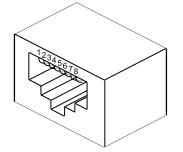
RJ45
MCX
Power Input
|
PIN1 |
12V |
|
PIN2 |
GND |
|
PIN3 |
54V |
|
PIN4 |
GND |
|
PIN5 |
GND |
|
PIN6 |
GND |
|
PIN7 |
AC Voltage monitor(1VAC/0.02VDC) |
|
PIN8 |
AC Current monitor(1.00A/1.00VDC) |
|
PIN9 |
54VDC Current monitor(1.00A/1.00VDC) |
|
PIN10 |
12VDC Current monitor(1.00A/1.00VDC) |
Digital Attenuator Control
PCB Placement
